![]()
![]()
![]() Visual Analyser Project
(vers. 25 Silvia edition )
Visual Analyser Project
(vers. 25 Silvia edition )

|
|
|
Un misuratore d'impedenza con compensazione automatica degli errori sistematici
Ho lavorato a questa nuova funzione di VA per oltre un anno, e credo sia impossibile per i più comprendere l'incredibile quantità di lavoro che ha richiesto. Probabilmente, se avessi saputo in anticipo a cosa andavo incontro avrei quasi certamente desistito. In qualche modo, siamo giunti alla fine (o forse ad un nuovo inizio) ed io sono veramente orgoglioso del lavoro fatto. E' stata per me un'occasione di imparare molte nuove cose, ed in tanti settori diversi. La colpa di tutto è di Nuova Elettronica che, subdolamente, mi ha coinvolto in questa avventura! ZRLC è dotato di un numero consistente di opzioni, e per ora è impossibile spiegarle tutte; fortunatamente, sin dalla versione beta, il programma ha attirato l'attenzione di molti appassionati, ed in particolare di Massimo Marucchi, che ha dedicato ad esso ben due articoli con tanto di realizzazioni hardware. La rivista Nuova Elettronica, con la quale ho collaborato per l'intero inverno, mi ha fornito idee preziose ed è arrivata a scrivere un ottimo articolo su ZRLC ed a proporre un kit a basso costo da abbinare a ZRLC. Faccio notare che la mia collaborazione con Nuova Elettronica non è a scopo di lucro, nell'ottica di quanto più volte ribadito nel sito. In questa pagina darò solo le informazioni base, facendo notare che il programma comprende (o comprenderà) il calcolo delle cifre significative, dell'incertezza (compito arduo!), auto-determinazione dei livelli del segnale, un semplice "Vettorscopio", filtri interni, possibilità di eseguire sequenze automatiche di misura nel dominio del tempo e delle frequenza. E moltissimo altro. Siate pazienti se per ora sono un pochino "criptico" ma il tempo è veramente tiranno. Un piccolo preambolo. Per il corretto funzionamento di ZRLC è necessario costruire un semplicissimo hardware aggiuntivo, allo scopo di ottenere prestazioni non solo "hobbystiche". L'hardware necessario è, in prima battuta, una semplice coppia di amplificatori operazionali usati in configurazione "adattatori d'impedenza" allo scopo di elevare il più possibile l'impedenza d'ingresso del misuratore. Questo per uno scopo relativamente ovvio: una bassa impedenza d'ingresso, caratteristica tipica delle schede audio, significa una perturbazione non trascurabile nel valore dell'impedenza da misurare. Ossia, in altri termini, misure poco accurate. Ancora un ulteriore preambolo. Nel cominciare questo lavoro sono stato ispirato da lavori esistenti, quali quello del Dr. George Steber ed altri lavori similari pubblicati dalla rivista Elektor (Dr. Klaper). Più altri minori o ugualmente validi, almeno di cui io sia a conoscenza. In prima istanza ho semplicemente riprodotto i loro lavori, costruendo un misuratore d'impedenza basato sull'algoritmo LMS (Least Mean Square), ossia quello universalmente utilizzato dagli autori succitati. Successivamente, ritenendo insoddisfacenti i risultati ottenuti, ho sviluppato una versione personalizzata che sfrutta le collaudate routine sviluppate in anni di lavoro su VA (per esempio l' FFT) con l'aggiunta di un algoritmo proprietario per la riduzione consistente degli errori sistematici più significativi. I risultati delle misure sono stati eccellenti; ho effettuato un confronto diretto con strumenti professionali del costo di svariate migliaia di euro, e devo dire che sono rimasto letteralmente esterrefatto. Prima di tutto, mi preme dire che ZRLC è stato progettato nello spirito di evitare, almeno alla prima esecuzione, di confondere (e scoraggiare) l'utilizzatore a doversi occupare di un numero enorme di incomprensibili settaggi e procedure. L'idea sarebbe quella di 1) costruire il circuito e collegarlo al PC 2) far partire VA e fare la misura. Non è cosa semplice, data la natura delle misure; io ho cercato il più possibile di rendere tutto automatico. Fate partire VA; l'unico settaggio che sarebbe opportuno controllare ed eventualmente modificare sarebbe la coppia "frequenza di campionamento" e "dimensione del buffer". Allo stato attuale ZRLC è ottimizzato per funzionare al meglio con la coppia 40960 Hz e 4096 punti di buffer, che è il normale default di VA. Se lo avete modificato, vi consiglio di aprire la finestra di Settings ed modificare i valori a quelli suggeriti (sotto-finestra "Main" , sulla sinistra). Con questa scelta viene attivato un meccanismo di calibrazione automatica più sofisticato di quello normalmente utilizzato. In ogni caso se userete una coppia qualsiasi (es. 44100Hz, 4096 punti), per frequenze di misura inferiori a 3000 Hz i risultati saranno comunque ottimi. Vi ricordo infatti che la misura di una impedenza è fatta utilizzando dei segnali di test di tipo sinusoidale, e dunque caratterizzati da una frequenza; la teoria dice che - per esempio - l'induttanza o la capacità NON dovrebbero variare al variare della frequenza (al contrario di altri parametri), ma naturalmente nel mondo reale intervengono molti altri fattori che più misure fatte a varie frequenze di test possono evidenziare. Il valore di frequenza di test che VA sceglie come default è 1000 Hz. A questo punto, selezionate la CheckBox ZRLC, che trovate nella finestra principale di VA, nella lista di CheckBox sulla destra dell'analizzatore di spettro. Appare dunque la finestra di ZRLC (vedi sotto), che automaticamente modificherà tutti i restanti parametri di VA per il suo funzionamento ottimale.
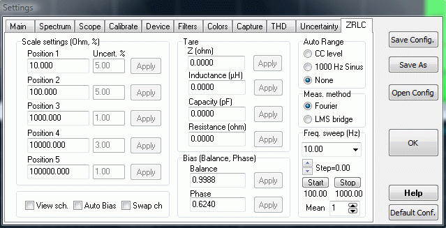
Tutti i settaggi di ZRLC potrete trovarli nelle solita finestra di Settings, ed in particolare nel "Tab" ZRLC, che riporto nella figura sottostante per comodità.
Diamo un veloce cenno al significato dei vari campi, prima di dare lo schema realizzativo del circuito base. Scale Settings: il circuito usato per la misura consente di realizzare uno strumento che "confronta" l'impedenza da misurare con una di valore noto; in particolare le portate sono cinque, determinate sperimentalmente secondo il criterio di massima fruibilità delle potenzialità dello strumento. Le cinque resistenze di riferimento dovrebbero avere i valori proposti come default (in Ohm), ma naturalmente nessuna resistenza reale assumerà esattamente quei valori. Di conseguenza è prevista la possibilità di impostare il valore "vero" della resistenza usata come campione; per esempio potrete determinarlo con un multimetro di precisione (magari preso in prestito). Da notare che l'accuratezza di misura sarà tanto migliore quanto accurata sarà la stima del valore delle resistenze di riferimento. In alternativa cercate di usare resistenze a bassissima tolleranza. In una prossima versione potrete inserire anche il valore della tolleranza stessa, consentendo a ZRLC il calcolo della corrispondente incertezza di misura. Viev sch. : consente di visualizzare il circuito necessario, lo stesso riportato più avanti. Ho preferito "cablarlo" in VA stesso per essere sicuro che ogni fruitore lo abbia sempre disponibile. Auto Bias: questa opzione, abilitata di default, consente di abilitare il meccanismo automatico di calibrazione, altrimenti si dovranno eseguire una serie di passi manuali. Raccomandata. Swap ch: consente di invertire, via software, i segnali applicati ai due ingressi della scheda di acquisizione. In pratica andrebbe lasciata disabilitata, ma se alla fine del montaggio hardware vi renderete conto di aver sbagliato, invece di mettere mano al saldatore potrete fare un test sfruttando questa opzione. In altre parole, "ceccando" questa opzione il segnale che avrete applicato ad un canale andrà all'altro e viceversa. Tare: questa sezione è in genere riempita automaticamente durante le normali operazioni di misura. In pratica, nella portata più bassa per ognuna delle tipologie di misura (Modulo impedenza, capacità, induttanza etc) c'è la possibilità di sottrarre alla misura la quantità che appare "a vuoto". Per esempio, nel caso di una resistenza, metteremo la portata più bassa (tipicamente 0.1 ohm..1000 ohm) e cortocircuiteremo i puntali. Successivamente premeremo il tasto "zero"; esso determinerà il valore dell'impedenza e lo memorizzerà per sottrarlo a tutte le successive misure. In altre parole, abbiamo misurato la resistenza dei cavi dei puntali, che naturalmente NON dovrebbe sommarsi alla misura della resistenza che stiamo testando. Dopo aver cliccato il tasto "zero" succedono due cose: la scritta cambia in "reset" ad indicare che una successiva pressione del tasto avrà ora la funzione di cancellare la "taratura" impostata; a fianco del bottone appare il valore (in ohm) che verrà sottratto ad ogni misura, anche quelle delle portate superiori. Non sarà possibile adoperare questo meccanismo alle portate più alte perché la misura di basse resistenze non sarebbe affidabile in portate che partono da misure già di per se elevate se comparate con l'ordine di grandezza della resistenza dei cavi. In caso di capacità adopereremo lo stesso meccanismo, ma lasciando il circuito aperto. Per tutte le altre dovremo cortocircuitare i puntali. I valori di "Tare" così determinati saranno automaticamente aggiornati nella finestra di Settings (ossia nei campi oggetto di questa spiegazione) e memorizzati alla chiusura del programma. Bias: sono i parametri automaticamente determinati quando clicchiamo il tasto measure, in una fase preliminare in cui NON dovremo connettere il DUT ai puntali (vedi spiegazioni in questa pagina). Essi rappresentano il coefficiente di ampiezza per bilanciare i due canali (ossia fare in modo che amplifichino in maniera identica) ed il coefficiente di fase per far si che sfasino esattamente della stessa quantità. Se NON è abilitata l'opzione AutoBias essi verranno determinati con una procedura semi-automatica (da spiegare!) e alla bisogna si possono modificare in tempo reale manualmente. Auto Range: opzione disponibile per future versioni con cambio scala automatico; è già disponibile a livello software, andrebbe pensata una realizzazione hardware. Meas Method: consente di selezionare il metodo LMS da cui sono partito a fare sperimentazioni, ed il metodo da me battezzato "Fourier". E' possibile passare da un metodo all'altro in tempo reale anche dalla stessa finestra ZRLC tramite il mouse, posizionandolo sul display principale e cliccando con il tasto destro. Freq Sweep: consente di impostare i parametri per una "sweeppata" in frequenza. Ossia è possibile effettuare una serie di misure in sequenza in maniera automatica nel dominio della frequenza. Serve ad impostare il valore di partenza e di fine della serie di misure (es. 1000Hz ..5000Hz) il passo (es. 100Hz) e la media. La media significa che ogni singola misura è ripetuta "media" volte e mediata algebricamente. Mi riservo spiegazioni molto più dettagliate in altra documentazione.
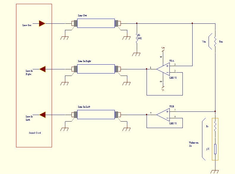
Il circuito Il semplice circuito da costruire è :
O simili. Vedi proposta di Nuova Elettronica o Massimo Marucchi, citati nella pagina principale di questo sito od alla fine di questa stessa pagina. Il circuito che indico è lo stesso proposto da Steber e la rivista Elektor, ma nulla vieta di usare componenti di migliore qualità o comunque schemi più complessi. L'idea di base per effettuare la misura è molto semplice; l'impedenza incognita è posta in serie ad una resistenza di riferimento; un segnale sinusoidale, esso stesso generato da VA, è applicato alla serie delle due impedenze. Per determinare le tensioni ai capi delle impedenze si usano i due canali di acquisizione delle scheda come indicato nello schema (le tensioni ai capi dei resistori sono calcolate internamente; i valori "prelevati" sono rispetto a massa, il passaggio è immediato). A questo punto è sufficiente applicare la legge di Ohm e l'impedenza incognita è determinata (il modulo). Per la determinazione della fase è anch'essa cosa immediata grazie alla trasformata di Fourier. Modificando il valore delle resistenze di riferimento è possibile variare la "portata" dello strumento; come anche suggerito da prove pratiche ho scelto i valori che si evincono dalla figura. I corrispondenti valori di portata per resistenza, capacità e induttanza sono calcolati di conseguenza, come si può osservare dalla listbox che serve per il cambio di portata. Da notare tuttavia un un fatto estremamente importante. Mentre le portate nel caso di misura di resistenza pura sono indipendenti dalla frequenza, lo stesso non può dirsi per bipoli con componente reattiva. Ossia, le portate variano in funzione della frequenza di test scelta, per esempio se si sta misurando una capacità. Implementare un algoritmo che modifichi il valore delle portate alla frequenza scelta non è cosa difficile, ma a mio avviso può trarre in inganno e rendere tutto molto complicato; le portate indicate sono pertanto fisse e relative al valore standard di 1000 Hz. Ricapitolando, le portate variano se si varia la resistenza di riferimento; dunque si può pensare a costruire un circuito dotandolo di un commutatore rotativo che consente di variare le portate selezionando rapidamente resistenze di riferimento differenti. Naturalmente, variando una portata in "hardware" si dovrà manualmente effettuare la commutazione su ZRLC tramite la listbox di cambio gamma. Invero, è stato previsto un meccanismo che predispone la realizzazione di un dispositivo a cambio gamma automatico. Infatti, uno dei canali di uscita, come è facile evincere dallo schema, rimane inutilizzato; pertanto può essere utilizzato per il cambio gamma. A tal proposito ZRLC genera un segnale a 1000 Hz di ampiezza variabile in funzione della portata che un algoritmo interno "decide" di utilizzare. Che dunque può essere utilizzato per pilotare una "batteria" di relè che fanno automaticamente il lavoro del commutatore rotativo. Ho proposto la cosa alla rivista Nuova Elettronica, ma l'uso di numerosi relè avrebbe alzato di parecchio il costo del kit. Lo stesso algoritmo è utilizzato per dare "suggerimenti" sul cambio di portata; quando la portata risulta insufficiente viene indicato tra parentesi una "d" o una "u" ad indicare che è necessario il passaggio ad una portata più bassa (d = down) o più alta (u = up). Se compare un punto interrogativo significa che l'algoritmo non riesce a decidere perché i segnali sono troppo bassi. Quest'ultima cosa può accadere in caso di malfunzionamenti, errati collegamenti o sovraccarichi. Le misure in pochi semplici passi Costruite il circuito e connettetelo alla vostra sonora come descritto. Lanciate VA e aprite la finestra ZRLC.
Che cosa si può misurare con ZRLC
Per ora è tutto. Sto cercando di scrivere più documentazione, mentre un validissimo articolo e corrispondente kit di un IMPEDENZIMETRO è stato approntato da Nuova Elettronica (rivista 242). Come già accennato più volte, Massimo Marucchi ha scritto un articolo che potrete visionare al link qui sotto . Scarica Articolo di Massimo Marucchi
Cliccare qui per uno screenshot di VA con ZRLC e "vettorscopio" in azione. |
Pubblicazioni recenti:
|
|
Invia una e-mail a
alfredo[at]accattatis.org in caso di domande o consigli sul sito.
|